APPLICATION
A construction company has a temporary office located in a remote area. Since commercial electric power from the local utility company is unreliable, a diesel powered generator is used during power outages. Fuel use in recent weeks has increased above expected levels, the project manager suspects that employee theft is occurring. One flow
sensor and three displays are needed to monitor fuel consumption. One display will be located near the generator, the others will be located in separate offices.
MCMILLAN PRODUCTS UTILIZED
220 Rate/Totalizer Displays
102-6-T-B6 Liquid FLO-SENSOR
100-17T Cable Assembly
DESCRIPTION
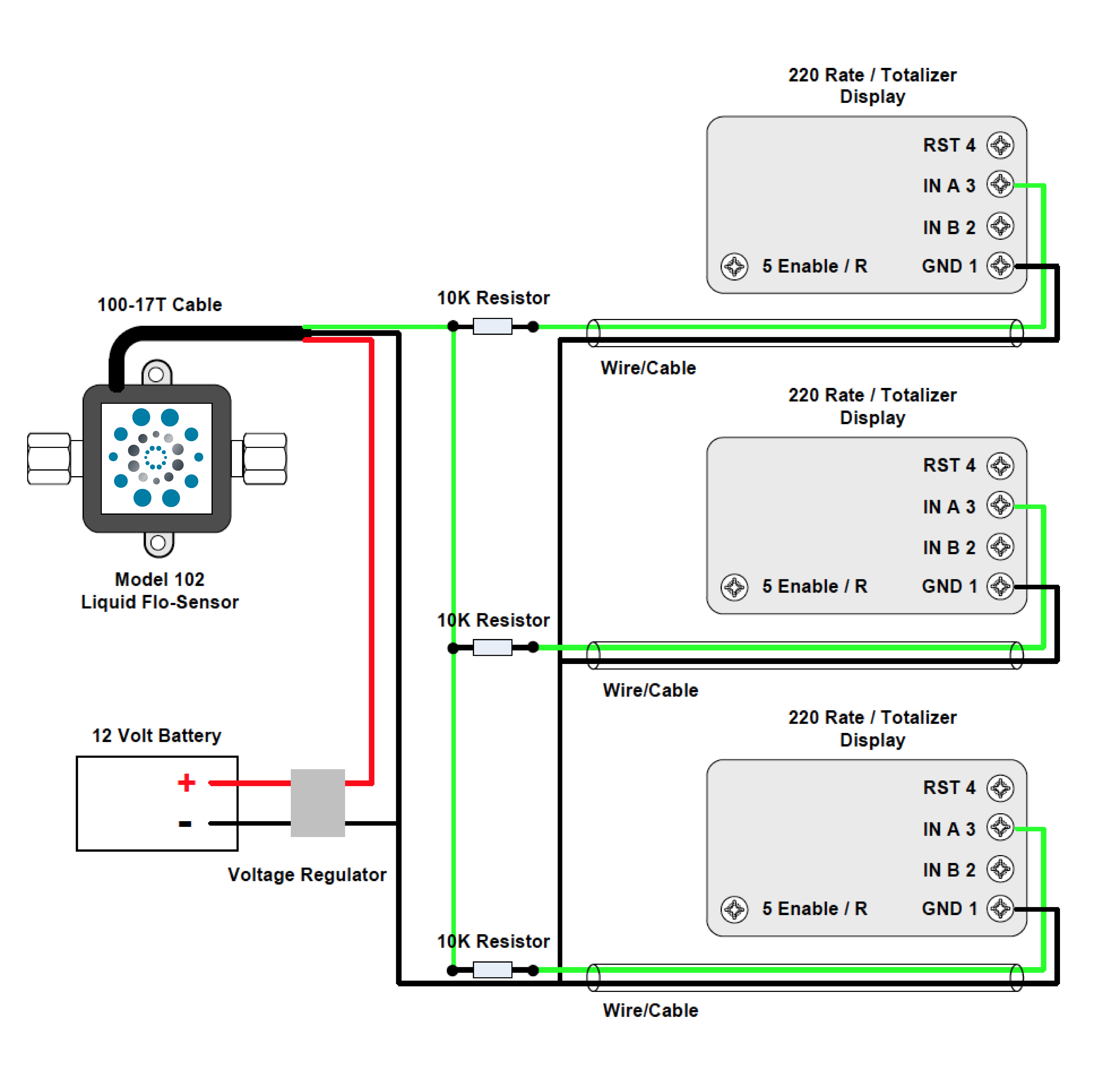
The McMillan 220 Rate/Totalizer Displays provide a visual reference for company employees and managers. The Model 102-6T Liquid FLO-SENSOR has a dual output, pulse and analog (0-5 VDC). This application will use only the pulse output signal. A 12 VDC battery powers the FLO-SENSOR. All connections to the sensor using a 100-17T Cable Assembly and 10K resistors are recommended to minimize the current draw on the pulse output circuit. (figure 2)
OPERATION
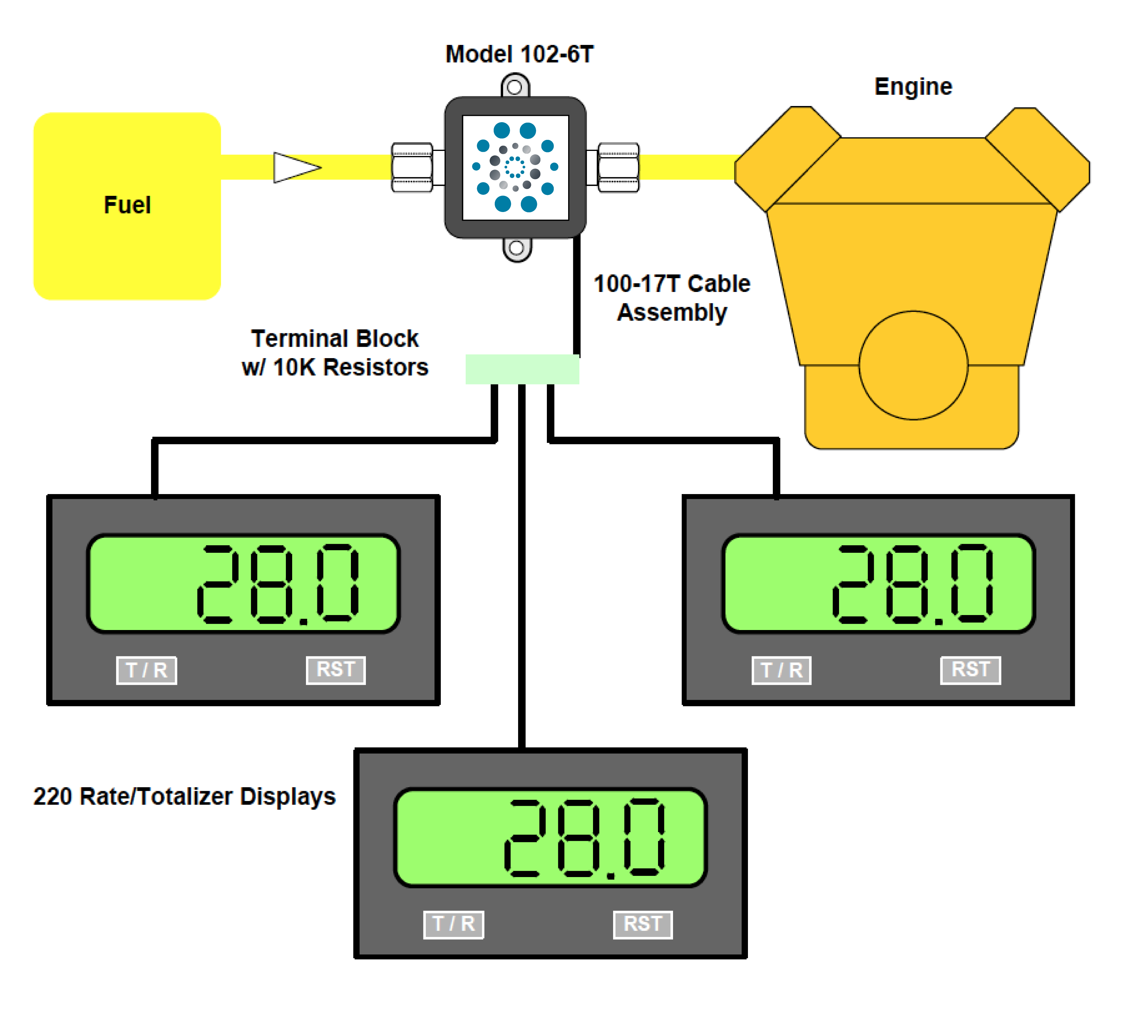
Diesel fuel to the engine is measured by the FLO-SENSOR, and recorded by the Model 220 Rate/Totalizer Displays.
ADVANTAGES
The Model 220 can display flow rate in fluid ounces, milliliters, liters, quarts or gallons per second, minute, hour or day. Flow total can be displayed in fluid ounces, milliliters, liters, quarts or gallons. The panel reset button can be disabled to prevent tampering with data collection. The Model 102-6T is constructed of brass. It has an accuracy of +/-1% Full Scale (Repeatability 0.2% Full Scale) and a maximum pressure rating of 500PSI.
DIAGRAM
Figure 1 illustrates the flow path of the fluid system. Figure 2 illustrates the wiring of the system.
FIGURE 1 – Flow Path of Fluid System

FIGURE 2 – System Wiring


