

APPLICATION
A manufacturer of diesel powered standby generators has received orders for generators with custom features. The end user, a healthcare facility, requires warning indicators for system malfunctions including low fuel flow. Fuel flow below 400mLpm is an early symptom of fuel filter clogging or fuel pump wear.
MCMILLAN PRODUCTS UTILIZED
501-6SC-S4-C3-F400 Liquid FLO-SWITCH
DESCRIPTION
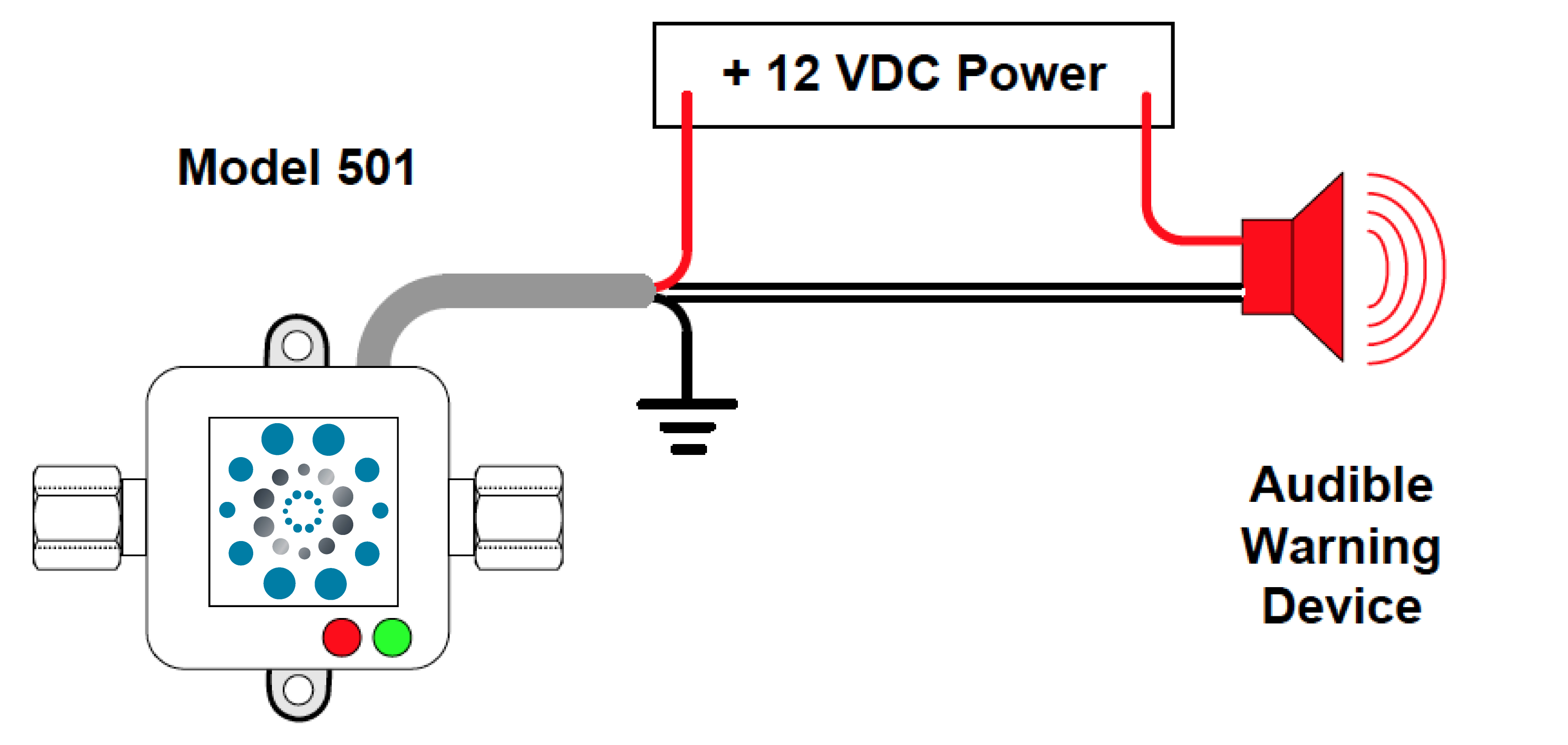
The McMillan 501 Liquid FLO-SWITCH provides a precision flow rate measurement on/off switch and visual LED references for the operator. Equipment system voltage 12VDC is used to power to the FLO-SWITCH via the integrated cable assembly.
OPERATION
Fuel flows from the tank through the Model 501 to the engine, excess fuel is returned to the fuel tank. The Model 501 and alarm are powered on while the engine is in start or run modes. During normal operation fuel flow is above the setpoint. The electronic switch in the Model 501 is open which interrupts the circuit to the alarm. When fuel flow is below the setpoint the electronic switch in the Model 501 will close, and the circuit to the alarm device will be complete thereby triggering the alarm*.
ADVANTAGES
The Model 501 Liquid FLO-SWITCH is capable of measuring low liquid flow rates from 13mL/minute up to 10L/minute. Materials of construction can be either plastic or metal. The integrated LEDs provide visual indication of power to the unit (green LED on), flow is detected (green LED pulsates), and the condition of the internal electronic switch, open (red LED off) or closed (red LED on). The internal setpoint is field adjustable using the integrated potentiometer or can be preset by the factory.
DIAGRAM
Figure 1 illustrates the flow path of the fluid system. Figure 2 illustrates the wiring of the system.
FIGURE 1 – Flow Path of Fluid System
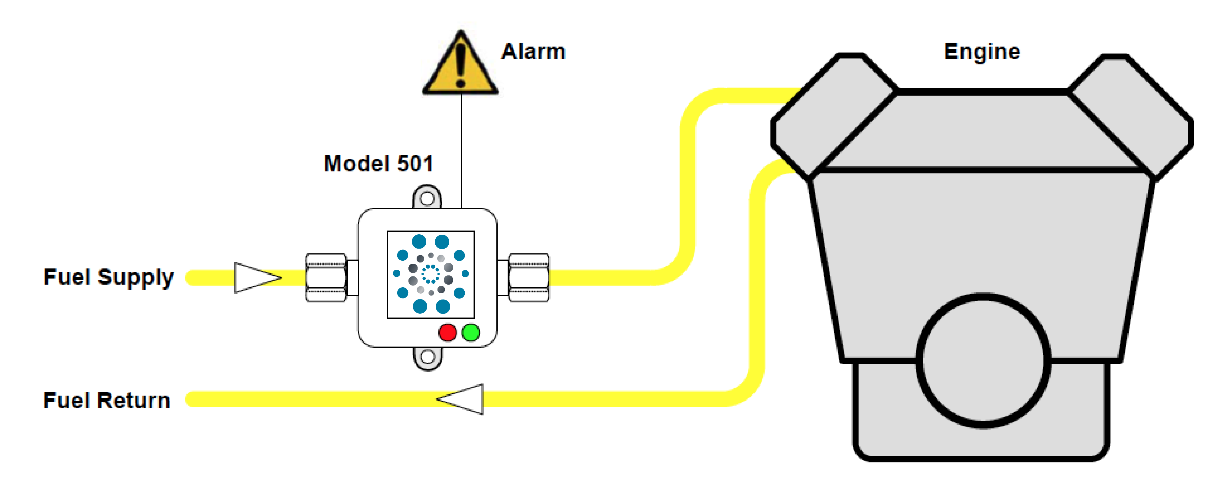
FIGURE 2 – System Wiring
*A relay is required if the alarm exceeds the power rating 24VDC/250mA of the Model 501. Contact the factory for
support.