
APPLICATION
A food processing plant must treat waste by-products prior to disposal. The by-products receive a measured quantity of chemical to promote decomposition. Chemical treatment is performed in a lift station located inside the plant.
MCMILLAN PRODUCTS UTILIZED
250 Multifunction Display
250-11 Alarm Output Card
104-9 Liquid FLO-SENSOR
100-17T Cable Assembly
DESCRIPTION
McMillan Multifunction Displays have many features. When combined with the optional Alarm Output Card, they can be used for accurate dispense applications. The Model 250 has an internal 12v power supply that provides power to the 104-9 FLO-SENSOR via the 100-17T Cable Assembly.
OPERATION
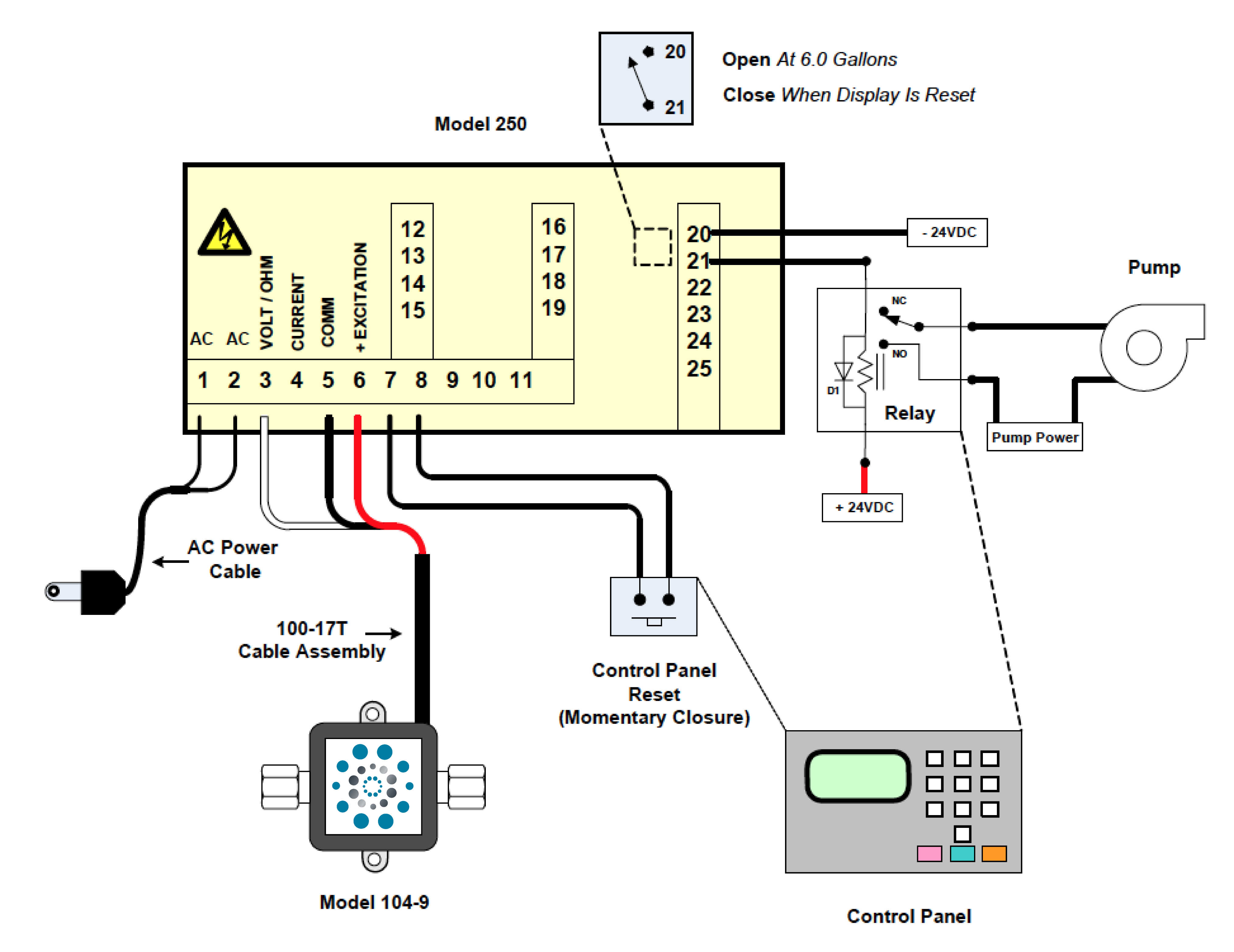
The control unit performs many functions for the application. Both the lift station and chemical tank are equipped with fluid level high/low sensors, pumps are monitored using current sensors. When the level of by-products in the lift station has reached a specific limit, the lift station will empty the contents into an outside storage tank. The details contained in this note will focus primarily on McMillan Company flow products. Upon determining that the lift station has been emptied, chemical will be dispensed into the lift station. The control unit will command the chemical pump on by resetting the Model 250. When six gallons of chemical have been dispensed the Model 250-11 Alarm Output Card will open the contacts, terminals 20 & 21. The control unit will then turn off the pump. Alarm Output Card contacts will remain open until the Model 250 is reset. The Alarm Output Card will fail safe (contacts open) should the Model 250 lose power.
ADVANTAGES
McMillan products provide accurate, repeatable measurement of low flow rates. The Model 250 Multifunction Display with the 250-11 Alarm Output Card is user friendly allowing the setpoint to be reprogrammed in the field if necessary. The combination of McMillan FLO-SENSOR and DISPLAY technologies provided a low-cost, high performance solution to this customer’s problem.
DIAGRAM
Figure 1 illustrates the flow path of the fluid system. Figure 2 illustrates the wiring of the system.
FIGURE 1 – Flow Path of Fluid System
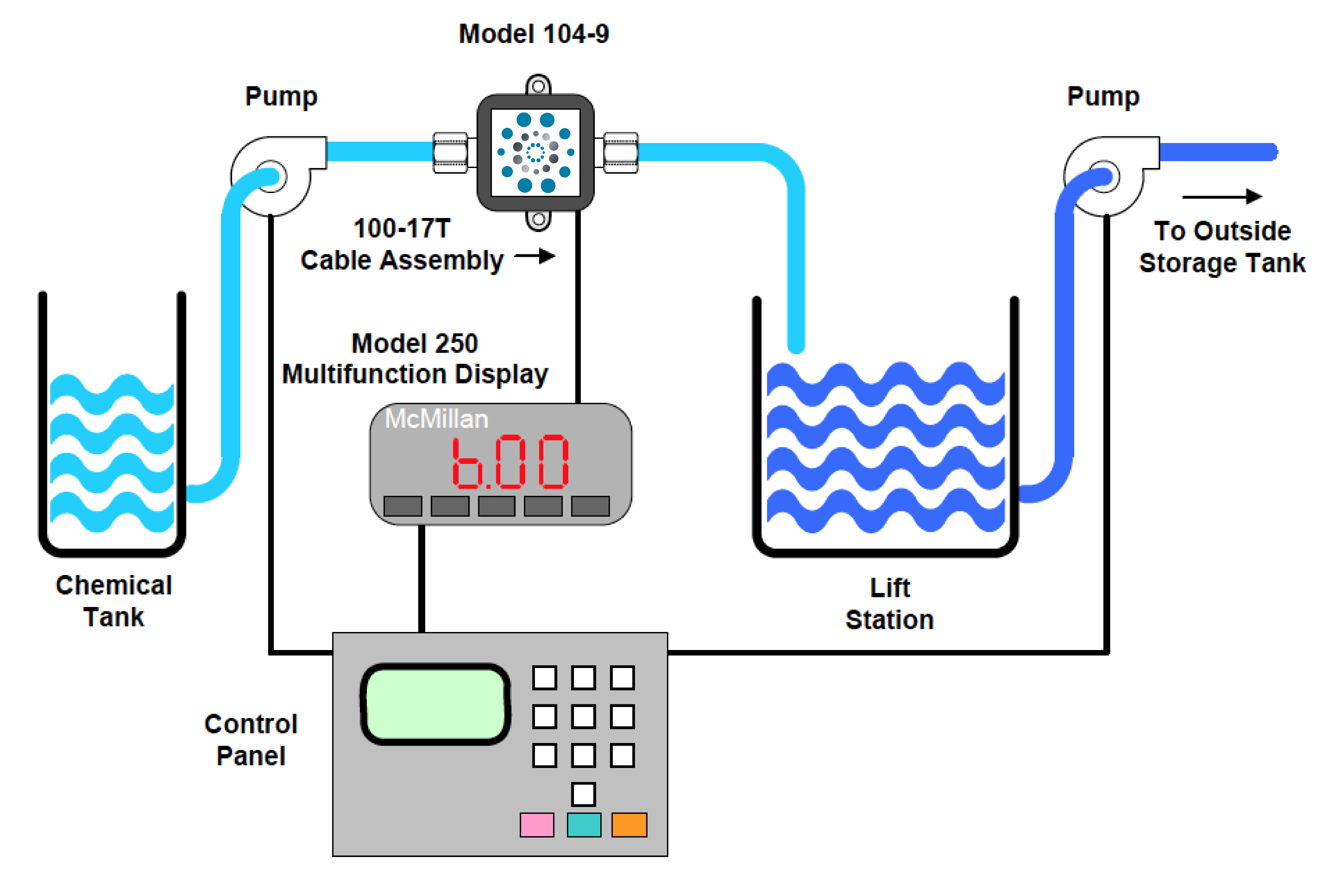
FIGURE 2 – System Wiring