
The Model 275 digital panel meter and display can be utilized in a variety of applications where a simple, easy to use, and versatile digital readout is required. The unit accepts 0-5 VDC signals (0-50VDC optional) and can be factory-programmed to read in various engineering units.


The Model 275 digital panel meter and display can be utilized in a variety of applications where a simple, easy to use, and versatile digital readout is required. The unit accepts 0-5 VDC signals (0-50VDC optional) and can be factory-programmed to read in various engineering units.
There are two mounting options to work in a variety of applications and panel setups. Various digit, display and unit configurations are available to ensure clear readouts for almost any application.
It is an excellent complement to the line of McMillan flow sensors and controllers, and can be wired using the same power source and 0-5 VDC output of most McMillan products. Consult with the factory for the best configuration of flow sensor and display.
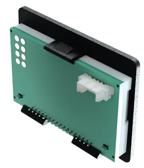
The Model 275 comes in two versions. The 275-A is designed to snap into a rectangular panel opening with small tabs on the top and bottom of the bezel. This is recommended for applications where access is easiest from the front of the panel and the panel will not be moved around, vibrating, or otherwise manipulated.
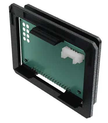
The 275-B utilizes a locking ring that is installed from the rear of the panel. This provides more security than the 275-A and should be used where rear access is possible. A larger range of panel thicknesses are also accommodated with this design.
Either unit can be removed from the panel and reinstalled as needed.
The factory can program the 275 Display to show a large variety of digits, decimals, and units. Units can be deleted to show a maximum number of digits, or time dividers can also be added (i.e. unit/time). These settings cannot be changed in the field.
A small 4-pin connector is provided on the back of the 275 display. Each display includes a 12 inch (30 cm) mating cable terminated in pigtail leads for easy connection.
The 275 can be powered with a DC supply as low as 5 VDC or as high as 26 VDC. It utilizes very little power and can even be run on a standard 9 VDC alkaline battery for as many as 110 hours.
Two signal configurations are available: 0-5 VDC or 0-50 VDC. For either range, the display will be set to read zero at 0 VDC and full scale at 5 VDC or 50 VDC, respectively.
The 275 Display is CE approved, RoHS-compliant and is NEMA 2/IP50 rated when installed in a panel.
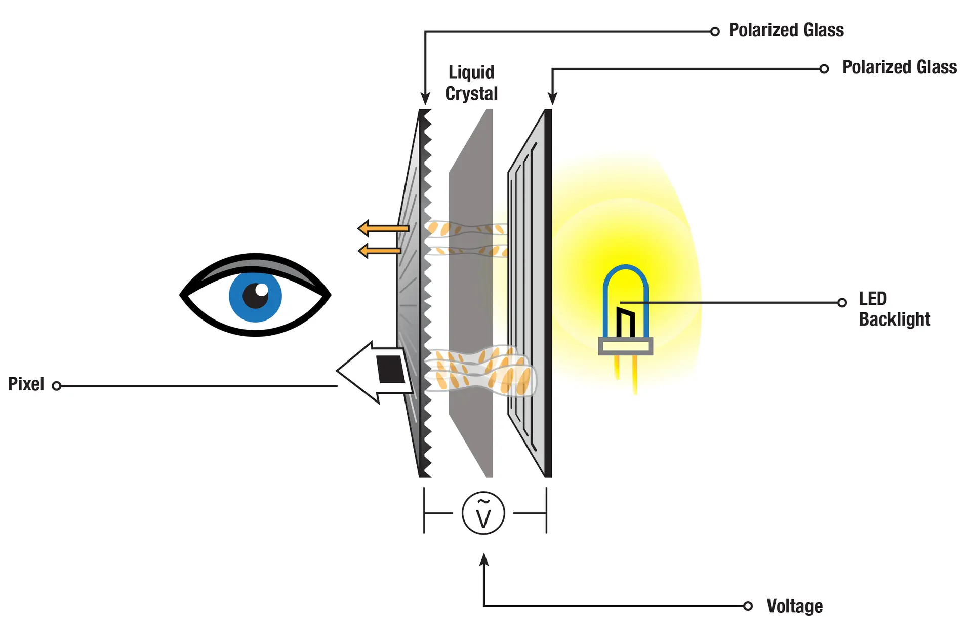
In order to understand how the Model 275 Digital Panel Display works, it is important to know how it is made. To start, LCDs are composed of two pieces of polarized glass. On the non-polarized side of the glass, a special polymer is added to create grooves that run in the same direction as the polarizing film. Once this is done, a liquid crystal material is added to the grooved side of one of the polarized glasses. These grooves align the liquid crystal with the glass. The second piece of glass is placed on top with the grooved side in, aligned perpendicular to the first pieces of glass creating a row and column arrangement.
Where the grooves of the two pieces of polarized glass intersect is a pixel. By blocking the light from passing through the top piece of glass, it creates an area that is darker than its surrounding. This gives the appearance of pixels being turned on or off. In order to block the light from passing though, the orientation of the liquid crystal has to be changed. To do this, an electric charge is needed. Without an electric charge, the liquid crystal is twisted which changes the angle of the light to match the angle of the top polarized glass. This allows the backlight to pass through that pixel.
When an electric charge is applied, the liquid crystal untwists leaving the angle of the light unchanged. This causes the light to be blocked by the top perpendicular piece of polarized glass. The controllers on the display will determine which pixels turn on and off. These controllers are programmed to translate input signal and display the value by activating appropriate pixels.
275-A (Snap-In Design)
275-B (Locking Ring Design)
LCD Technology
15-bit, +/-0.02%
32 x 8mm (1.25” x 0.31”)
128 x 32 pixels
NEMA 2, IP50
White LED
200-250 mS
5 samples per second
Displays “OVR” at 5% beyond rated input voltage
All units are calibrated at the factory; recalibration is recommended in 12 month intervals for the highest accuracy
Approximately 20Kohm impedance, 0VDC represents 0, 5VDC represents full scale
Approximately 250Kohm impedance, 0VDC represents 0, 50VDC represents full scale
5-26 VDC, reverse polarity protected, 60-90 milliwatts
-20 to 60°C (-4 to 140°F)
-30 to 80°C (-22 to 176°F)
0 to 90% non-condensing
4-wire connector, 30cm (12”) pigtail adapter included
1 year limited
| Categories | Title | Summary | File Size | Download |
|---|---|---|---|---|
| Data Sheets (PDF) | DISPLAY_DS-275 2502 A.pdf | Latest data sheet for the Model 275 | 2 MB |
We are experts in all things flow. As a company founded and run by engineers, we seek to understand your application and then build a product solution that will solve your most difficult challenges.

McMillan Flow sales agents are strategically located across the
globe. Find your nearest distributor or office.
McMillan Company
7075 Ranch Rd 2338
Georgetown, TX 78633
sales@mcmflow.com
Phone: (844) MCM-FLOW
Copyright © 2025 McMillan Flow Products. All Rights Reserved.
McMillan Flow Products is located in the U.S.A. and all products are manufactured in our Texas plant.
"*" indicates required fields